The Problem of coexistence
Most consumer radio products (think 802.11b/g/n, a.k.a WiFi, Bluetooth, Zigbee, Thread…) nowadays somehow make use of the ISM band around 2.4GHz. This band was chosen by multiple technologies for a series of reasons, the prominent one being that it’s unlicensed. Its success, however, brought with it a key problem as well: overcrowding and interference. While most of us have experienced inter-device interference (ever scanned for WiFi and got back a list of 666 networks in range?), a more subtle form is what you could call intra-device interference, i.e. that experienced by devices that host more than one radio. The typical example in consumer electronics would be devices that support both WiFi and Bluetooth, but more esoteric combinations exist.
The problem is simple to understand: let’s say you have a WiFi radio with its antenna and a Bluetooth radio right next to it with its own antenna. They don’t know about each other, so there is a high chance that they might transmit at the same time (the higher their combined duty cycle, the higher the chance) If they do, and if they happen to be transmitting close in the frequency domain, their transmissions will interfere with each other.
Mitigation strategies
Interference is usually solved by multiplexing over whichever domain possible.
Physical separation
Physical domain multiplexing would be a fancy expression for “keeping the antennas far from each other”, which is one of the best practices in designing these systems. However, this approach is usually limited by the size of the product you’re designing. If the PCB is a few centimeters long, that’s as far as you can place antennas.
Frequency separation
Frequency domain multiplexing can potentially help a lot more. A good example of this is channel management in 802.11b/g/n: the 2.4GHz spectrum is divided in up to 14 channels (or as few as 11 in certain countries) each with a bandwidth of 22 MHz and a channel separation of 5 MHz, and WiFi access points select the channel that looks the least busy. Bluetooth uses a more dynamic approach called frequency hopping, in which the spectrum is split into a high number of channels and the radios jump from one to another following a pseudo-random pattern. This makes it less likely that a single, strong source of interference can disrupt a connection; however, a “uniformly” noisy 2.4GHz environment, or a very close source with strong harmonics, will still be an issue. 802.15.4 (the standard on which Zigbee and Thread are based) uses 16 channels, (unintuitively) numbered from 11 to 26, with a bandwidth of 2 MHz and a channel separation of 5 MHz. Channel management is similar to WiFi, with the whole network being on the same channel and no frequency hopping. Channel changes are allowed, but a policy on when and how to do that is not standardised.
Packet Traffic Arbitration as a solution
PTA (Packet Traffic Arbitration) tries to help with time domain multiplexing. What that means is that one of the radios can act as a master, the other as a slave, and the master will decide (arbitrate) access to the air medium to avoid that the radios transmit (or, to a degree, expect to receive) something at the same time. PTA is described in IEEE 802.15.2 (2003) Clause 6. However, PTA is a recommendation, not a standard, so implementations vary in the details. The most common form of it uses 3 signals, usually called REQUEST, PRIORITY and GRANT.

The slave can assert REQUEST to signal that it needs to access the air medium. Optionally, it can assert PRIORITY to influence the master’s arbitration in its own favour. The master is responsible of asserting GRANT in response when it sees fit. This is where implementations diverge in the details of how this decision is taken. Some keep GRANT asserted whenever they are not transmitting, even if REQUEST is not asserted. Others will GRANT immediately on REQUEST if the medium is free, otherwise complete their transmission and then GRANT. However the GRANT happens, once it is asserted the slave will transmit and de-assert REQUEST when the medium is no longer required. This is also implementation dependent, as some slaves will de-assert immediately after transmitting while others, expecting an immediate reply, will wait some time before releasing the medium. There are also 4 wire (using an extra FREQ signal), 2 wire (omitting PRIORITY) and 1 wire (using just GRANT) variations, which are however less common. In any case, the master role is usually assigned to the WiFi radio in the system, as WiFi is usually the technology with the highest duty cycle among the ones involved.
Getting practical with the CYW43143 and EFR32
For a series of reasons, PTA has not been used much recently. The most frequent use case (certainly the one that shifts the biggest amount of ICs) would be Bluetooth + WiFi in laptops and mobile phones, which is better served by so called combo chips. These integrate 2.4GHz WiFi, Bluetooth and 5GHz WiFi in one package, eliminating the need for PTA traces between 2 chips while also saving on BoM cost and PCB surface, which are both at a premium on mass marketed, portable devices. However, in a recent design we needed to do PTA at all costs. The system had the CYW43143 WiFi 2.4GHz radio (originally by Broadcom, then acquired by Cypress, in turn acquired by Infineon). The other 2.4GHz technology involved was Thread, a mesh network stack based on 802.15.4 (same as Zigbee) and IPv6. This of course ruled out a wifi-bluetooth combo chip. Our radio choice was a Silicon Labs EFR32. The board was based on an Allwinner A13 SoC running a heavily customised build of OpenWrt. The board already followed best practices to separate the antennas and frequency separation does not help much (Thread is less frequency-agile than WiFi, in which Access Points can move channel at any point in time); as a result, interference did occur frequently and PTA came to the rescue. Kind of.
Enabling PTA
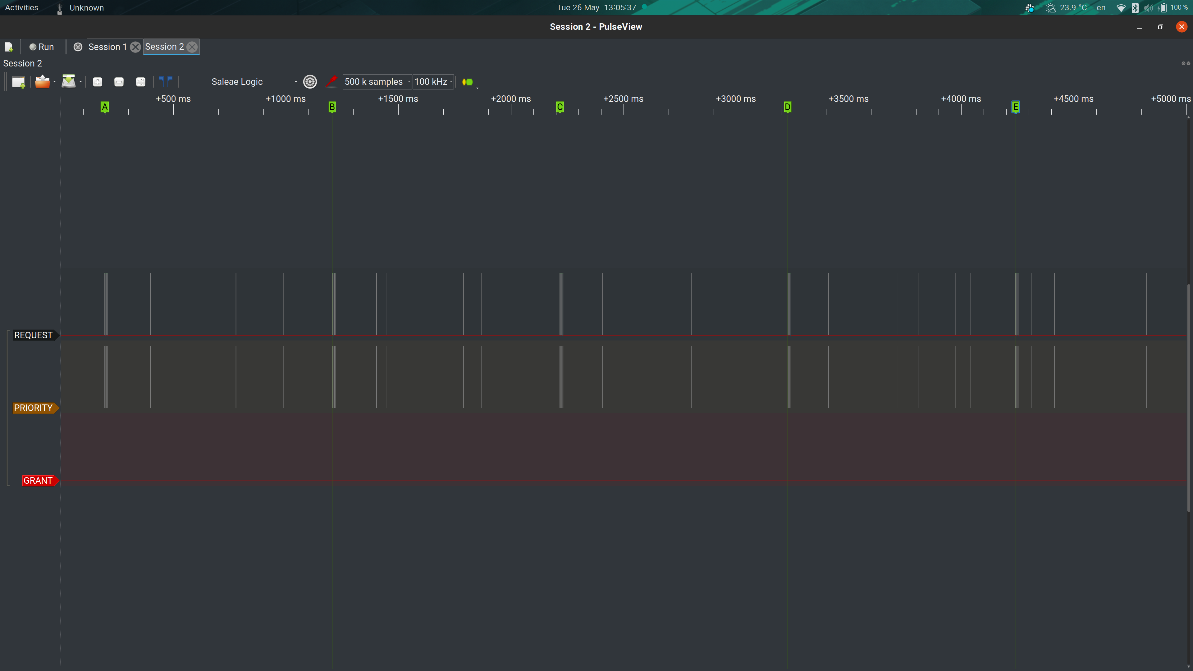
The EFR32 played nice; Silicon Labs provides several libraries (called plugins) with its Thread stack, and one of them is a PTA library, which can be configured to use up to 3 wires, with different polarities, different request logics etc. The only significant limitation is that it only implements slave logic, but that was not a problem in our case (the 43143 only implements a master, so they fit perfectly). After a bit of configuration and a rebuild, the EFR32 was using REQUEST and PRIORITY as expected, as verified with a logic analyser (via the trusty sigrok!).

First trouble
As you can see from the GRANT line trace above, though, something was wrong on the other side. Despite running a ping at 1Hz on the Thread network, the (active low) GRANT line being stuck low meant that the 43143 was essentially not doing any arbitration and always giving the go ahead. This was the result of ignorance and (wrongly) assuming that the functionality would be enabled either by the brcmfmac driver that we used, or by the firmware that is loaded to the 43143 when the brcmfmac module is loaded. Here begins the trouble. The Cypress application note about coexistence (AN214852) covers both the proprietary, Cypress-only SECI interface (which can only be used between Cypress chips) and the “standard” PTA interface, and for the latter it mentions that certain NVRAM parameters need to be set.
USB – SDIO disagreements
So far so good, except that setting NVRAM parameters is not as straightforward as you might hope. A look at the brcmfmac kernel module code shows that for SDIO chips, the module will load a firmware blob from /lib/firmware/brcm and an nvram.txt file with NVRAM parameters. Easy peasy. In our system, however, we use a USB interface to the 43143, and unfortunately the approach the brcmfmac module takes for USB chips is different: only a firmware blob is loaded, no trace of an nvram file. So, PTA requires custom NVRAM, the IC is USB and the USB code does not use an NVRAM file: kind of a nasty roadblock, since I (again, wrongly) thought that modifying the blob was a no-go.
brcmfmac/usb.c (note argument 1 is 0 and argument 3 is NULL, meaning nvram file is not loaded)
/* request firmware here */
ret = brcmf_fw_get_firmwares(dev, 0, brcmf_usb_get_fwname(devinfo), NULL, brcmf_usb_probe_phase2);
if (ret) {
brcmf_err("firmware request failed: %d\n", ret);
goto fail;
}
brcmfmac/sdio.c (note argument 1 is BRCMF_FW_REQUEST_NVRAM, argument 4 is not null)
ret = brcmf_fw_get_firmwares(sdiodev->dev, BRCMF_FW_REQUEST_NVRAM, sdiodev->fw_name, sdiodev->nvram_name, brcmf_sdio_firmware_callback);OpenWrt to the rescue
Thanks to the help of a couple of folks (PaulFertser and rmilecki) from the #openwrt-devel IRC channel on freenode, however, I had a couple of lucky breaks. First, the blob that is loaded for USB devices is a fairly standard TRX binary format.
$ ./otrx check brcmfmac43143.bin
Found a valid TRX version
Second, the blob contains the nvram parameters as zero terminated ASCII strings, and they are all just appended at the end.
$ strings brcmfmac43143.bin

[SNIP]

extpagain2g=0
pdetrange2g=0
triso2g=3
antswctl2g=0
maxp2ga0=82
mcsbw202gpo=0x75333333
mcsbw402gpo=0x97544444
legofdmbw202gpo=0x75310000
cckbw202gpo=0x1111
swctrlmap_2g=0x0a050a05,0x0a050a05,0x00000000,0x00000000,0x000
xtalfreq=20000
otpimagesize=154
tempthresh=120
temps_period=5
temp_hysteresis=5
rssismf2g=0x8
rssismc2g=0x8
rssisav2g=0x2
loopbw2g=100
txalpfpu=1
aci_detect_en_2g=1
rxgaintempcoeff2g=60
$
Together with otrx, a TRX format editor/checker written by rmilecki, this allowed me to use an hex editor to alter the blob and add the parameters from AN214852. Easy, right? Nah.
Decyphering the scripture

Almost all we have about these parameters. Note that beyond the names, their function is not described
Unfortunately, there is no documentation about said parameters outside of AN214852 and, even there, you are only given an example for a “4343W board” without explaining how to adapt them to other board or what they do specifically. Of course the example parameters for the 4343W did not work on the 43143, so some guesswork was needed.

As you can see in the logic trace above, using the values in the AN, the GRANT line was being toggled once in a while, and it was no longer stuck low. A sign that PTA was enabled, but something more was wrong. In fact, you can also see that the GRANT line was only sporadically toggling. Time to dig into the meaning of coexistence parameters from the AN:
boardflags=0x1
zbcxpadnum=0x040201
zbcxfnsel=0x233
zbcxgcigpio=0x123
and a few lines below, this slightly confusing addition:
Boardflags=0x00000001 /* SECI coex */
Boardflags2=0x00000080 /* Board support legacy 3/4 wire */
This is accompanied by the following parameter bit maps:

The slightly cryptic information about the PTA parameters in NVRAM
EDIT 2021-01-28: as it turns out, our board had the REQUEST routed to GPIO0 (due to a misunderstanding in design). What you read in this post was written before we realised that. It all worked because apparently the 43143 actually IGNORES the pins selected via zbcxpadnum and always expects the REQUEST signal on GPIO0. This is especially surprising since the application note says on page 4:
Note: WL_GPIO_0 is normally reserved for WLAN_HOST_WAKE or interrupt events, and therefore is not recommended for coexistence hardware interface.
I guess the AN was written with other chips in mind and the 43143 is an exception? Anyway, back to the original post.
So, the general idea was that boardflags and boardflags2 would enable coexistence, and they should be set to 0x01 and 0x80 to do so. zbcxpadnum was reasonably simple: a the bitmap makes it obviously about which GPIO is used by which signal. On our board, GRANT is on GPIO1, PRIORITY on GPIO2 and REQUEST on GPIO4, so this needed to be changed to 0x010204.
zbcxgcigpio is kind of a mystery still: the AN only mentions GCI, which seems to stand for Global Coexistence Interface, but says nothing more about it. From a quick Google search it seems GCI is a serial protocol, so this is probably not related to us. However, not defining this parameter seemed to go back to GRANT being always low. For lack of better understanding, I set it to the example value of 0x123.
The key problem however was hiding behind zbcxfnsel, which controls, it seems, the muxing of different functions to different pins. The example of 0x233 is not correct for the 43143, on which the PTA functions seem to be on position 3 for all GPIOs, probably giving us a value of 0x333 for zbcxfnsel. This is a guess, since as you can see in the screenshot below, the 43143 datasheet does not specify the value. However, the “Legacy BT coexistence” function is always listed in 3rd place, so I decided to give it a go.

Functions of GPIOs on the 43143 (from the original datasheet)
Taking it for a spin
Let’s add the parameters we decided above to the binary:

hex view of the contents of the firmware blob after adding our parameters
Now, TRX has a CRC, so these changes make the CRC wrong; luckily, otrx prints out both the expected and the computed CRC:
$ ./otrx check brcmfmac43143.bin
Invalid data crc32: 0x4dc00fe3 instead of 0x2a665d76
Let’s fix the CRC (taking into account the binary endianness, we need to reverse the CRC bytes)

hex view of the firmware blob after fixing the CRC
Now, let’s place this new binary in /lib/firmware/brcm/ and do a cold reboot (because brcmfmac will skip downloading the firmware if one is running already) to let the kernel module load the new binary.
A test with iperf3 running on the wifi interface while pinging a host on the Thread network shows the following:

GRANT line doing its job!
As hoped, the 43143 is now a PTA master and the EFR32 correctly honours the GRANT signal.